
Getting an accurate PCB assembly (PCBA) quote is essential to managing costs, timelines, and quality expectations. A precise quote depends on multiple factors such as the accuracy of design documentation, clarity in assembly type, component sourcing strategy, and access to board fabrication suppliers. From prototype runs to low-to-mid production volumes, aligning quote requests with IPC guidelines (e.g., IPC-A-610, IPC-2612, IPC-1752) helps ensure consistent communication and expectations between OEMs and contract manufacturers.
Key Factors Affecting PCB Assembly Quotes
1. Bill of Materials (BOM) Accuracy
The BOM must be in Excel format and should include:
- Manufacturer and distributor part numbers
- Detailed component descriptions (e.g., capacitors, resistors, ICs, discrete semiconductors)
- Specified quantities, voltage/current tolerances, and part ratings
- Reference designators
- Approved vendor list (AVL) or cross-reference suggestions for alternates
A clean, validated BOM reduces quoting delays, sourcing confusion, and potential cost escalations.
2. PCB Design Files and Technical Drawings
For accurate quoting, assemblers rely on standardized data formats per IPC-2581 or Gerber files. Designers should submit the following:
- Gerber files: Complete with drill data and layer stack-up
- ODB++ or IPC-2581: Optional, but increasingly preferred for intelligent data exchange
- Centroid (XY) file: For automated pick-and-place programming
- Assembly and fabrication drawings: Include mechanical outlines, fiducials, special instructions, and layer callouts
- Schematics: Aid in process review and troubleshooting
Well-prepared documentation reduces NPI delays or costly rework.
3. Assembly Complexity and Process Type
Labor and equipment costs scale with assembly difficulty. Clearly indicate:
- Technology type: SMT, Through-Hole (THT), or Mixed Technology
- Component density: High I/O BGAs, fine-pitch ICs, PoPs, or micro BGAs may require X-ray or 3D AOI
- Double-sided assembly: Adds handling steps and complexity
- Lead-free compliance: If required, specify RoHS per IPC-A-610 Class 2 or 3
Rework considerations: Identify any areas requiring manual rework or non-standard operations
4. Component Sourcing and Availability
Component procurement plays a significant role in cost and lead time:
- Define whether the job is Turnkey, Consigned, or Partial Consignment
- Provide sourcing constraints (e.g., authorized distributors only)
- Specify alternate parts if original components are long lead or obsolete
- Collaborate with EMS providers that offer AVL management and strong supplier networks
5. Testing and Inspection Requirements
Include test strategies and inspection standards during the quoting phase:
- AOI: Automated Optical Inspection for SMT components
- X-ray: Mandatory for BGAs and bottom-terminated components (BTCs)
- Flying Probe Test
- FCT: Functional Circuit Testing based on the end-product use case
- First Article Inspection (FAI): Often required in aerospace, defense, or automotive per IPC J-STD-001
More comprehensive testing improves yield but adds both time and cost.
6. Lead Time
Specify:
- Turnaround expectations: Standard lead times, quick-turn, or expedited builds
- Bare board availability: Include expected fab lead time if not bundled with assembly quote
Be aware that compressed schedules often require faster component sourcing, kitting, and machine setup, which can affect cost.
Tips for Maximizing Quote Accuracy
- Use standardized formats: IPC-2581 or ODB++ enable streamlined quoting
- Double-check part availability: Avoid EOL or constrained components
- List acceptable alternates: Increases sourcing flexibility
- Specify industry class: IPC-A-610 Class 2 (standard), Class 3 (high reliability)
- DFM feedback: Use a manufacturing partner that performs DFM checks on every order. Proactive design reviews can prevent yield losses
An accurate PCB assembly quote is the product of detailed planning, clear communication, and standards-based documentation. By aligning your BOM, design files, and test requirements with IPC guidelines and supplier expectations, you create a smoother quoting process and reduce risk throughout the production lifecycle. Whether you’re working on PCB prototypes or scaling into volume production, a robust and well-documented quote request is a critical step for a successful project.
Learn more about Summit’s assembly services and submit files for a quick quote.
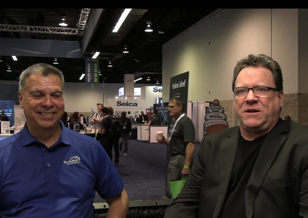
At IPC APEX EXPO 2025, Gerry Partida, VP of Technology at Summit Interconnect, sat down with Andy Shaughnessy, to discuss a critical yet often overlooked aspect of PCB manufacturing: sustainability. The conversation explored the impact of design choices on sustainability, and the importance of collaboration between designers and fabricators.
The Overlooked Role of Sustainability in PCB Design
While many companies are now asking about sustainability initiatives, few designers actively consider the environmental impact of their designs. Summit Interconnect actively works to reduce its environmental footprint. For instance, the company recently installed new lamination presses that use induction and magnetic fields instead of traditional hot oil boiler presses. These advanced systems consume only 20% of the energy compared to older methods, significantly reducing the environmental footprint.
However, Partida noted that customers often don’t consider sustainability in their designs. In many cases, Summit analyzes a PCB design only to find that poor design choices reduce yield to 50%, forcing manufacturers to double production efforts, doubling energy consumption, material usage, and labor costs. This inefficiency highlights the need for early collaboration between designers and fabricators.
How Design Choices Impact Sustainability
One major takeaway from the discussion is that many designers are unfamiliar with fabrication standards and guidelines. Partida shared an example where a group of PCB designers was asked if they had read the industry’s design guidelines, and fewer than 20% had done so. Without this knowledge, designers inadvertently create complex and inefficient layouts, leading to increased scrap rates, excessive material usage, and unnecessary production strain.
By following PCB design standards for rigid, flex, and RF boards, designers can:
- Improve yield efficiency, reducing waste.
- Enhance reliability and performance while using fewer resources.
- Lower manufacturing costs by avoiding unnecessary rework.
Collaboration: The Key to Smarter, Sustainable Design
A recurring theme in the conversation was the importance of communication between designers and fabricators. Many sustainability issues arise when designers bend the rules without understanding fabrication limitations. Partida encouraged designers to work closely with fabricators early in the process, ensuring that minor adjustments can be made without compromising efficiency, compliance, or manufacturability.
He shared an example where a client tried to fabricate a board with unrealistic standards, only realizing too late that they needed to redesign their approach. By engaging fabricators early, design teams can avoid costly mistakes and ensure that PCBs are built efficiently and sustainably.
The Future of Sustainable PCB Design
As the PCB industry evolves, sustainability is becoming an essential factor in manufacturing, supply chain management, and design processes. Summit Interconnect is leading the way by investing in:
- Energy-efficient manufacturing techniques.
- Automated systems to reduce waste.
- Training initiatives to educate designers on sustainability best practices.
Partida closed the discussion by encouraging PCB designers to take a more proactive approach to sustainability, not only for the benefit of manufacturers but also for cost savings and long-term industry success.